CONTENTS
1.2 Purpose of the Safety Management Plan
1.3 Structure of the Safety Management Plan
2....... Safety Management System..
2.2.1....... Operational Safety & Standard Committee
2.2.2....... 3-tier Site Supervision
2.6 Controls of Hazardous Gas Area
2.7 Accident / Incident Investigation
2.10 Accident Control and Hazard Elimination
3....... Key Safety Design Features
3.3 Access Control and Work Control in a Hazardous Gas Area (HGA)
3.7 Overpressure and Blowdown System
3.8 Subsea Pipeline Protection
4....... Operation and Maintenance (O&M) Procedures
4.2 O&M Mobilisation Team Structure
4.5 Isolating the BPPS Pipeline
5....... Emergency Response Procedures
5.1 General Emergency Response Strategy
6....... Marine Safety Arrangement and Procedures
7....... Regular Safety Review and Audit
List of Tables
Table 2.1 Audit Process for Operational Safety
Table 2.2 Emergency Drills in BPPS
Table 3.1 Overview of Pipeline Construction Methods and Trench Designs
Table 4.1 O&M Manuals and Procedures
Table 4.2 Roles and Responsibilities of the O&M Mobilisation Team
Table 5.1 Type of Gas incident & Corresponding Emergency Response
List of Figures
Figure 1.1 Indicative Location of Key Project Components
Figure 2.1 3-tier Site Supervision Structure
Figure 2.2 3-tier Site Supervision Structure for Out-sourcing Work
Figure 2.3 Training Framework & R&R
Figure 3.1 Trench Design (Type A)
Figure 3.2 Trench Design (Type B)
Figure 3.3 Trench Design (Type C)
Figure 3.4 Trench Design (Type D)
Figure 3.5 Trench Design (Type E)
Figure 3.6 Trench Design (Type F)
Figure 3.7 Trench Design (Type G)
Figure 3.8 Trench Design (Type 1)
Figure 3.9 Construction Methods for the BPPS Pipeline
Annex
To support the increased use of natural gas in Hong Kong from 2020 onwards, Castle Peak Power Company Limited (CAPCO) and The Hongkong Electric Co., Ltd. (HK Electric) have identified that the development of an offshore liquefied natural gas (LNG) receiving terminal in Hong Kong using Floating Storage and Regasification Unit (FSRU) technology (‘the Hong Kong Offshore LNG Terminal Project’) presents a viable additional gas supply option that will provide energy security through access to competitive gas supplies from world markets. The Project will involve the construction and operation of an offshore LNG import facility to be located in the southern waters of Hong Kong, a double berth jetty, and subsea pipelines that connect to the gas receiving stations (GRS) at the Black Point Power Station (BPPS) and the Lamma Power Station (LPS). The location plan is shown in Figure 1.1.
The Environmental Impact Assessment (EIA) Report for the Project was submitted to the Environmental Protection Department (EPD) of the Hong Kong Special Administrative Region Government in May 2018. The EIA Report (EIAO Register No. AEIAR-218/2018) was approved by EPD and the associated Environmental Permit (EP) (EP-558/2018) was issued in October 2018. An application for Further Environmental Permits (FEP) was made on 24 December 2019 to demarcate the works between the different parties. The following FEPs were issued on 17 January 2020 and the EP under EP-558/2018 was surrendered on 5 March 2020:
§ the double berth jetty at LNG Terminal under the Hong Kong LNG Terminal Limited, joint venture between CAPCO and HK Electric (FEP-01/558/2018/A) ([1]);
§ the subsea gas pipeline for the BPPS and the associated GRS in the BPPS under CAPCO (FEP-03/558/2018/B) ([2]); and
§ the subsea gas pipeline for the LPS and the associated GRS in the LPS under HK Electric (FEP-02/558/2018/A) ([3]).
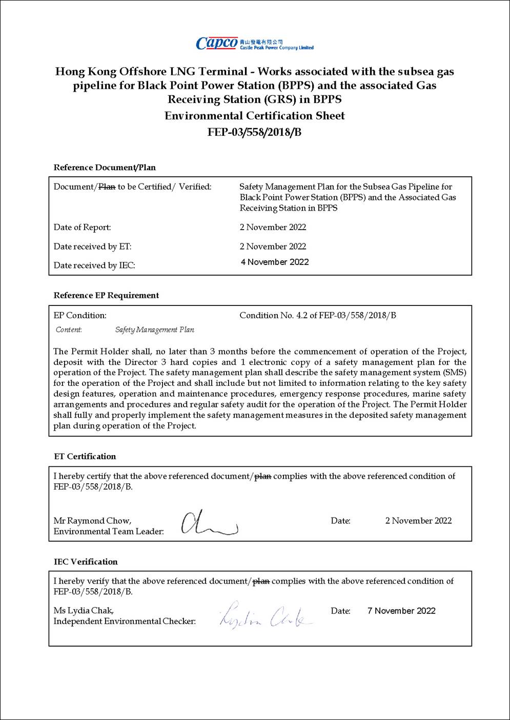
In accordance with Condition 4.2 of the FEP of the subsea gas pipeline for the BPPS and the associated GRS in the BPPS (FEP-03/558/2018/B) (‘the Project’):
|
FEP No. FEP-03/558/2018/B, Condition 4.2: “The Permit Holder shall, no later than 3 months before the commencement of operation of the Project, deposit with the Director 3 hard copies and 1 electronic copy of a safety management plan for the operation of the Project. The safety management plan shall describe the safety management system (SMS) for the operation of the Project and shall include but not limited to information relating to the key safety design features, operation and maintenance procedures, emergency response procedures, marine safety arrangements and procedures and regular safety audit for the operation of the Project. The Permit Holder shall fully and properly implement the safety management measures in the deposited safety management plan during operation of the Project.” |
As stated in Condition 4.2 of the FEP, this Safety Management Plan presents the safety management system (SMS) for the operation of the Project, including information relating to the key safety design features, operation and maintenance procedures, emergency response procedures, marine safety arrangements and procedures and regular safety audit for the operation of the Project.
This Safety Management Plan covers the facilities of the BPPS Pipeline connecting from the LNG Terminal Jetty (not including the Jetty itself) up to and inclusive of the GRS in the BPPS.
The remainder of this Safety Management Plan is set out as follows:
§ Section 2 presents the safety management system for the operation of the Project;
§ Section 3 describes the key safety design features of the Project;
§ Section 4 details the operation and maintenance (O&M) procedures of the Project;
§ Section 5 presents the emergency response procedures;
§ Section 6 presents the marine safety arrangement and procedures; and
§
Section 7 presents
the mechanism for regular safety review and audit.
Generation Business Group (GBG) of CLP Power Hong Kong Limited (CLP Power) covers three power stations, i.e. Black Point Power Station, Castle Peak Power Station and Penny’s Bay Power Station. The GBG Management System ensures the incorporation of safety precaution and requirements in the special procedures or instruction in compliance with relevant statutory requirements and the CLP Power Safety Rules.
The safety management system described in the following sections refers to various GBG Management System standard, Generation Business Group Instructions (GBGI), as well as the Generation Business Group Procedures (GBGP) currently in effect for the commissioning, operation, and maintenance activities relevant to the existing facilities and new facilities of the BPPS of the Project.
CLP Power cares for the safety and health of our employees, contractors, customers and the public. Therefore, in order to ensure Zero Harm in the workplace and everyone goes home safely, the aim is to achieve zero exposure at all of the work locations with the following commitments:
§ Eliminate exposures which may lead to serious injuries and fatality;
§ Uphold safety and health as an integral part of our work and a value that is never compromised;
§ Develop a proactive, positive and interdependent team safety culture amongst our employees and contractors, such that we all work safely and support each other in CLP Safety Family, and issues are communicated openly, fairly and with mutual respect;
§ Provide a safe and healthy environment for all who work on or visit our premises;
§ Use Plan-Do-Check-Act approach to proactively manage safety and health as an integral part of our work processes and activities, including the demonstration of innovative ways to improve the safety management;
§ Comply with the requirements of all applicable safety and occupational health laws and regulations;
§ Define clear accountability and responsibility for safety at all levels of the organization, reinforcing the idea that we all have a responsibility to work safely. Management must lead by example and provide continued and visible support to safety;
§ Continuously enhance the knowledge, competence, awareness and behaviour of the management, our employees and contractors in safety and hazard management, through sharing and exchanging knowledge and experience;
§ Actively pursue continuous improvements on safety performance through executing targeted, defined safety initiatives and establishing challenging measurable objectives and targets while regularly reviewing performance;
§ Execute “Fair and Just Culture; and Nurture an off-the-job safety and health culture.
The Safety and Health Policy is provided in Annex A.
The GBG Operational Safety & Standard Committee (the Committee) comprising senior managers from relevant departments is established to steer the overall strategies in effective implementation of the operational safety requirements, with support from GBG Operational Safety & Standard Work Team. Assurance of operational safety requires that management leadership and commitment is visible throughout the organisation, and, managers at all levels are made accountable.
The Committee will:
§ formulate policy and steer the implementation of the statutory & corporate requirements, CLP Power Safety Rules, GBG specific requirements & safety codes of practices in relation to operational safety;
§ support and contribute to the promotion of the operational safety culture;
§ review operational safety performance and make recommendations for improvement;
§ approve amendments / changes to work practices;
§ appoint Operational Safety Work Team Chairman and members.
The membership includes:
§ Chairman
o Deputy Director – Castle Peak Power Station
§ Core members
o Director – Black Point / Penny’s Bay Power Stations
o Director – Generation Engineering
o Director – System Operation
o Senior Manager – Safety, Health, Environment and Quality
o Safety & Health Manager
o Operation Safety Manager
o Learning Institute Training Manager
o Senior Production Manager – Black Point/Penny’s Bay Power Stations
o Senior Production Manager – Castle Peak Power Station
The roles, responsibilities and accountability of all levels of staff, either permanent or under short term contract and 3-tier Site Supervision personnel within the Generation Business Group (GBG) with respect to safety are defined. The 3-tier Site Supervision Structure under Safe Systems of Work (SSoW) is developed in GBG, in order to provide a clear understanding of roles and responsibilities in site supervision. Employees or contractors involved in site supervision also have their responsibilities under the 3-tier Site Supervision Structure.
The 3-tier Site Supervision Structure and 3-tier Site Supervision Structure for Out-sourcing Work are presented in Figure 2.1 and Figure 2.2, respectively. Safety Training
CLP Power will provide formal gas training, on-the-job training and refresher training for their owned gas facilities, including the BPPS Pipeline and the associated GRS of the Project. Managers will participate in the training. Managers and supervisors will promote staff awareness through discussion, and will ensure that staff attend formal safety training. Safety information relating to employee's scope of work should be made readily available for reference. Levels of training are determined by the duties of an individual on the gas system. Training must be refreshed periodically. All the safety training record will be kept properly.
The expected results of the safety training are:
§ employee’s experience, knowledge, training, and skills match with their job position;
§ specific tasks that requiring specific knowledge, skills, tools, experience and proper attitude are performed by duly authorized persons.
The training framework and Execution Roles and Responsibilities (R&R) are presented in Figure 2.3.
Before the commercial operations of GRS and the BPPS subsea pipeline, training for the operation and maintenance staff have to be completed. Other than basic Safety, Health and Environment induction training, newly recruited staffs will go through the BPPS operator certificate check book system to acquire relevant knowledge on GRS and BPPS subsea pipeline. For new operators, GBG instructions on operator competency are applied and relevant training is provided per training needs analysis outcome.
CLP Power Safety Rules, GBG procedures, GBG Instruction, Operating Instructions, Maintenance Specifications are developed and constantly reviewed to ensure work safety and compliance with the latest legal and company requirements, including different types of authorized persons and their respective responsibilities.
Supervisors are responsible for the followings:
§ Understand the work procedure applicable to their areas;
§ Ensure work requiring safety document(s) are authorized, issued, and received prior to the commencement of work;
§ Ensure appropriate training is given to workers for their understanding of the safety document management procedure and special precautions prior to commencement of activities;
§ Ensure conditions and precautions specified in safety documents are strictly followed;
§ Ensure close-out and sign-off of the safety documents after completion of the job.
Individuals working within the system are responsible for the followings:
§ Possess a reasonable understanding of safety document procedures at their working location;
§ Possess a detailed working knowledge of the safety documents procedure applicable to their jobs;
§ Understand that they should not start any work requiring a safety documents until one has been authorized;
§ Ensure that the conditions and precautions specified in safety document issued to them for any work involved are understood and are strictly followed.
To ensure the thorough understanding of the safety rules and the correct use of safety documents, all authorized persons are trained and appointed in writing by CAPCO after being assessed in accordance with the requirements stipulated in Authorization of Personnel for Operational Duties; Safety Requirements on Hot Work Process; Modular Safe Work Procedure for Safe Working in Confined Spaces; and Natural Gas Authorisation.
Regular safety audits are useful to check performance against expectations. Deviations from standards set in the procedures and policy, unsafe act and conditions; unauthorized changes will be within the scope of the audit. They are conducted by staff trained and appointed to carry out this task.
A summary of the various means of safety audit process with the corresponding scope and measurement is provided in Table 2.1.
Table 2.1 Audit Process for Operational Safety
|
Audit Process |
Scope |
Indicator |
|
Half-yearly Operational Safety Audit |
Scope extended to cover the end-to-end operational safety review (WSWP/Method Statement, permit issuance, isolation and site verification) |
§ Calculate number of good against discrepancies; § No. of discrepancies identified, analysed and categorized to suggest proposal for improvement |
|
Monthly Operational Safety Audit |
Focus in 5 categories: Switching practices, isolation integrity, preparation of Safety Document (SD), SD handover process, SD recipient performance |
§ Calculate number of good against discrepancies; § No. of discrepancies identified, analysed and categorized to suggest proposal for improvement |
All observations/deviations are recorded in the database. Reviews are conducted at the Management Review Meeting to ensure the follow-up actions will be completed and close-the-loop.
Within the Power Stations, including the GRS of the Project, owned by CAPCO, there are systems normally operating with flammable materials for power generation. In the vicinity of these systems, formation of flammable atmospheres is possible. These areas are classified as hazardous with the boundaries determined in accordance with the concept of Hazardous Area Classification. Potential ignition sources within such areas must be controlled by the specification of recognized and certified safe equipment and, adoption of specific working practices to eliminate the risk of fire or explosion initiation.
The Power Stations, including the GRS of the Project, owned by CAPCO adopt the Hazardous Gas Area (HGA) Classification as a formal practice in the operation and maintenance of systems for flammable liquids, gases and vapours which can produce a potentially explosive atmosphere, including hydrogen, LPG, natural gas, and distillate. Distillate oil with flash points well above 54ºC, is not regarded as flammable liquids under the scope of area classification except in the vapour space of in-service oil tanks.
The objective of the hazardous gas area classification is to distinguish plant areas into zones within which the progressive risk of an explosive gas/air mixture is demarcated. An area classification can also provide a basis for the selection of electrical apparatus appropriate to the degree of potential risk involved.
Hazardous areas are classified according to their perceived likelihood of hazard. There are three zones of classification.
§ ZONE 0: Zone in which an explosive gas/air mixture is continuously present or present for long periods;
§ ZONE 1: Zone in which an explosive gas/air mixture is likely to occur in normal operation;
§ ZONE 2: Zone in which an explosive gas/air mixture is not likely to occur in normal operation, and if it occurs it will exist only for a short time.
When the hazardous areas of a plant have been classified, the remaining areas will be defined as non-hazardous areas. Personnel entry and work inside hazardous gas area should require adequate appropriate training and competence. Power industry best practices are adopted in GBG for safety access precautions and work associated with the flammable gas systems.
The following summarises the major components of the process regarding controls of working in HGA:
§ HGA classification & determination of types of zones;
§ Entry into HGA & work inside a HGA;
o General operating procedures
o Special Precautions
§ Temporary declaration of a HGA to Non-HGA;
§ Training and competency of personnel; and
§ Maintenance precautions.
Only competent personnel with the required safety documentation should carry out work inside a HGA. Personnel competent to operate and/or maintain a flammable gas system (except natural gas, where separate authorization applies) should have completed the training on gas safety awareness.
Approved Gas Worker (AGW), Natural Gas Competent Person (CP(NG)) and Natural Gas Senior Authorized Person (SAP(NG)) are authorized to enter into a HGA. Other personnel requiring entry into a HGA shall be directly supervised by a CP(NG) / SAP(NG). All personnel entering the HGA should carry an approved personal gas monitor suitable for flammable gas system (in addition to other PPE in working instruction related to the task).
All work should be carried out according to relevant operating and maintenance procedures approved by the Branch Head and agreed by the duty Senior Shift Manager.
A standard procedure for responding to natural gas incident includes the following:
§ Reporting a gas leak, gas fire or any natural gas pipeline/facility damage from the residents nearby, members of the public or CLP employees;
§ Designation of the report centre;
§ Description of expected actions, communications, investigating, reporting and post incident following up steps.
According to Clause 15.a to 15.c of Chapter 51 of Gas Safety (Registration of Gas Supply Companies) Regulations, the Director or his delegated representative shall, on a major gas emergency:
§ Report the emergency to the Gas Standards Office (GSO) within 2 hours;
§ Provide the GSO with such information and details in relation to the emergency as he requires;
§ Furnish a written report on gas emergency no later than 28 days after the Incident.
Immediate verbal report (per Clause 15a) and written report (per Clause 15c), on gas emergency to the GSO should be directed to the Gas Standards Office of the Electrical and Mechanical Services Department (EMSD).
All incidents related to gas plant must be documented, investigated and corrective actions followed up and implemented.
A report will be compiled by the investigation panel on the exercise. Recommendation will be made to improve the response if necessary. Focus is on the effectiveness of all parties on:
§ Communication;
§ Coordination;
§ Correct use of relevant procedure; and
§ Use of safety equipment.
Emergency preparedness and response are essential to ensure that, in the event of an incident, all appropriate actions are taken to minimize the impacts on staff, contractor, public, environment, company assets and Company’s image. Public confidence in the integrity of our operations is important. Maintaining contact with the community during normal and abnormal event is a key factor in retaining their confidence.
Preparation for emergencies also considers as a high priority for the protection of health and safety of all employees and contractors that works and the public that live near to company facilities or operations. Emergency drills are developed to test the preparedness of personnel and to generate confidence and experience to deal with emergencies. There are various types of emergency drills in BPPS for which these drills are carried out at regular frequencies, provided in Table 2.2.
Table 2.2 Emergency Drills in BPPS
|
Type of Drills |
Frequency |
Description |
|
Fire/Evacuation Drill |
Twice every year |
One of these two drills is to be held with the participation of Fire Services Department. Safety & Health Manager of Safety, Health, Environment, & Quality (SHEQ) Department or Station SHE officer is responsible to make co-ordination with any outside authorities as well as internal parties in Black Point to involve on the drill. |
|
Shift Emergency Drill |
Due to annual drill plan |
Duty Senior Shift Manager is responsible to conduct this drill under regular frequencies. The drill is to be involved with other relevant parties within GBG such that the involvement of other parties can be practiced on a regular basis. |
|
Oil Boom Deployment Exercise |
Once every year |
This exercise can be carried out in line with the regular refilling of station fuel oil tanks by oil barge to the station. Duty Senior Shift Manager is responsible for conducting this drill. |
|
Gas Pipeline Leak Simulation Drill |
Once every year |
BPPS Fuel and Gas Team is responsible to co-ordinate and makes arrangement for the drill. |
|
Cyber Security Drill |
Once every year |
A simulation drill carried out together with BPPS Process Control Team. BPPS Process Control Team will simulate the scenario of cyber-attack at the control system of a non-running unit to test the respond of the operator on detecting and responding to the cyber-attack. |
A coordinator is usually nominated to make necessary co-ordination of such drills. To support the effective management of emergency preparedness, effective voice and data communication links should be established between assets, regions and the Group.
Table-top drill will be conducted by BPPS as for staff familiarization on the BPPS subsea pipeline emergency response plan actions before the commercial operations.
The execution of Operational Safety System is also applicable to all contractors and all other persons while on CLP Power premises, or, when working on or near the power system, plant or apparatus, under the control of CLP Power.
All Contractors’ workers are responsible for:
§ understanding and adhering to policies and Health & Safety principles and concepts;
§ providing comments and suggestions to improve GBG Management systems and /or procedures and safety and health performances;
§ carrying out activities assigned according to procedures to implement and execute GBG Management Systems.
The operational safety management system covers the management of potential higher risk operations with special procedures or instructions for the protection of personnel requiring to work or test on the systems, plant or apparatus under the control of the company at work sites of GBG. The system ensures the incorporation of safety precaution and requirements in the special procedures or instruction in compliance with relevant statutory requirements and the CLP Power Safety Rules.
The approach for achieving gas safety including the following major components:
§ Segregation of ignition sources from explosive gas;
§ Identification of hazards and operability problems of a process using HAZOP (Hazard & Operability Assessment) tool;
§ Establishment of techniques for leak prevention and minimization;
§ Emergency response and incident investigation;
§ Safety audit and management involvement.
Earthing/grounding rules and procedures specify the requirements to ensure precautions are taken prior to execution of work on electrical equipment, including checking that equipment are fully isolated from any power supply source and earthing of equipment to ground to discharge residual current is in place.
Any work involving removal of any gas apparatus from the system, the content gas must be purged with carbon dioxide or nitrogen in accordance with GBG Procedure - Purging flammable gases, vapours & liquids prior to removal. A satisfactory purge must be confirmed using suitable test equipment. The system must also be satisfactorily purged by carbon dioxide or nitrogen in accordance with GBG Procedure to remove air prior to refilling with gas and re-commissioning.
All the inert gas for purging must be pre-certified for purity by the gas supplier and have the certificate verification on receiving from supplier.
HGA is a designated area for fixed plant installations in which flammable gas may be present and within which special precautions during work inside these areas shall be adopted.
Where physical barrier is available, painting or clamp plates of the same pattern should be applied where considered practicable. Warning signs in both English and Chinese should be displayed at a prominent position at each entrance of the Hazardous Gas Area. The signboard should contain symbolic signs and warning messages.
Prior to entering, a Permit-To-Work in conjunction with a Risk Assessment Report and Confined Space Entry Certificate must be issued.
When it is necessary to work on live electrical equipment in HGAs, then the area must have been tested to prove the absence of a flammable explosive mixture. A Limited Work Certificate shall be issued and the personnel carrying out the work shall have an intrinsically safe personal gas monitor set to alarm at 20% Lower Explosive Limit (LEL) at all times. Equipment likely to cause ignition (i.e. meggers test) can only be taken and used in a HGA at gas-free condition.
The plant access control of various HGA location can refer to the local procedure, GBG Instruction – Plant Area Access Control & Restricted Area Access Control of respective stations.
Fire and flammable gas detectors are provided at the GRS area to detect events of fire and flammable gas leakage. Firewater ring main system, firewater monitors, fire hydrants and hose reels are provided at the GRS area.
Based on the location of all HGAs, the type and the quantity of firefighting equipment should be determined according to the risk of the systems, periodically inspected and recorded according to the station procedure.
Inside the natural gas control areas, anti-static clothing will be used as directed. Fire extinguishers should be placed readily available where work is being carried out. The automatic fire protection systems are provided in gaseous fixed firefighting protection areas.
Process control valves (e.g. pressure control, temperature control etc.) are provided in the GRS area in order to continuously maintain the stability of the overall process operation. Process deviation alarms are also provided to alert the operators to take necessary actions.
Emergency Shutdown (ESD) system is provided at the GRS area in the event of an emergency and to return the system to a safe, static condition so that any remedial action can be taken. The ESD system can be activated automatically through various process initiators and manually through push buttons. The inlet emergency shutdown valves (ESDV) are provided in the GRS to isolate the inventory in the event of emergency situation as such the leakage of the hazardous material can be controlled and minimized.
Pressure control valves are provided at the GRS area to maintain the pressure of natural gas in the process system. However, in the event of overpressure, the blowdown system is designed to vent automatically from a point downstream of the pressure reduction station to a vent stack. A CO2 snuffing system is installed to extinguish the vent if the gas is ignited by lightning or other causes.
It is a requirement that all subsea pipelines in HKSAR waters must be buried below the seabed. Burial depth when considered with rock armour provides the required level of pipeline protection. The actual burial depth below seabed is dependent on the marine and subsoil conditions along the pipeline routes. For areas that are considered to pose a threat to the integrity of the pipeline through anchor drop/drag, additional protective measures are required such as rock armour placement. The pipelines would be externally coated with an anti-corrosion coating and would also be concrete weight coated. The pipeline trench designs have been developed to provide the range of pipeline protection required for the BPPS Pipeline. Each of them is described below:
§ Trench Type A: This trench is formed by JETTING (see Figure 3.1);
§ Trench Type B: This trench is formed by JETTING (see Figure 3.2);
§ Trench Type C: This trench is formed by JETTING (see Figure 3.3);
§ Trench Type D: This trench is formed by JETTING (see Figure 3.4);
§ Trench Type E: This trench is formed by JETTING (see Figure 3.5);
§ Trench Type F: This trench is formed by DREDGING (see Figure 3.6);
§ Trench Type G: This trench is formed by DREDGING at the top 1.5m and then by JETTING of 6.5m further for the subsea cable sterile corridors (see Figure 3.7);
§ Trench Type 1: This trench is formed by DREDGING (see Figure 3.8).
Table 3.1 Overview of Pipeline Construction Methods and Trench Designs
|
Description |
Section Length [km] |
KP (km) |
Trench Type |
Construction Method |
|
|
From |
To |
||||
|
Pipeline Riser |
0.1 |
0.0 |
0.1 |
Type A |
Dredging |
|
Jetty Approach to South of Soko Islands |
8.8 |
0.1 |
1.49 |
Type B |
Jetting |
|
1.49 |
2.75 |
Type G |
Dredging, followed by Jetting |
||
|
2.75 |
3.55 |
Type E |
Jetting |
||
|
3.55 |
4.43 |
Type G |
Dredging, followed by Jetting |
||
|
4.43 |
8.9 |
Type C |
Jetting |
||
|
Southwest of Soko Islands |
3.2 |
8.9 |
12.1 |
Type C |
Jetting |
|
Adamasta Channel |
3.5 |
12.1 |
15.6 |
Type C |
Jetting |
|
Southwest Lantau |
5.7 |
15.6 |
21.3 |
Type C |
Jetting |
|
West of Tai O |
4.9 |
21.3 |
26.2 |
Type C / D |
Jetting |
|
West of HKIA |
5.3 |
26.2 |
31.5 |
Type E |
Jetting |
|
Sha Chau to Lung Kwu Chau |
6.0 |
31.5 |
37.5 |
Type C |
Jetting |
|
Lung Kwu Chau to Urmston Anchorage |
3.6 |
37.5 |
41.1 |
Type C |
Jetting |
|
Urmston Road |
1.8 |
41.1 |
42.9 |
Type F |
Dredging |
|
West of BPPS |
2.0 |
42.9 |
44.9 |
Type E |
Jetting |
|
Pipeline shore approach at BPPS |
0.1 |
44.9 |
45.0 |
Type 1 |
Dredging |
|
Note: (1) No more than two jetting machines would be used for the construction of the subsea gas pipeline of the Project. In addition to existing relevant mitigation measures, the minimum separation distance between the two jetting machines for avoiding cumulative impact is 5km for most of the pipeline sections, except when one jetting machine is working at the subsea cable sterile corridors (i.e. KP1.49 – KP2.75 and KP3.55 – KP4.43). When one jetting machine is working at the subsea cable sterile corridors, no other jetting machine will work concurrently within KP0.0-KP14.25, i.e., between the Jetty and Adamasta Channel. |
|||||
The GRS and BPPS subsea pipeline will be operated and maintained by BPPS O&M team with corresponding O&M strategy.
The O&M strategy is developed to describe the organization, implementation and setting up plan of the operations and maintenance team, covering the procedures, business systems and supporting O&M infrastructure of the existing and new GRS and BPPS subsea pipeline. The strategy has been developed and being implemented to align with the operational and maintenance readiness of the relevant parties.
The O&M strategy focuses on the following but not limited to:
§ Develop O&M contracts for critical materials and services for operations;
§ Develop O&M procedures and relevant documentation for development and review;
§ Develop training requirements and approach for O&M staff;
§ Organise proper logistics & infrastructures and support for GRS and BPPS pipelines operation;
§ Ensure all the required permits, licenses and certifications for operation are in place;
§ Arrange operational readiness assessment during mobilization;
§ Conduct safe and effective performance test in coordination with the contractor/licensors before provisional acceptance of the facilities.
The preparation and readiness of the O&M procedures mainly incorporates the following elements as shown in the table below:
Table 4.1 O&M Manuals and Procedures
|
O&M Manuals |
System Operating Manual |
Overall Plant Operating Manual |
Maintenance Procedures |
|
§ System functional description § Technical data of system components § System control logic |
§ System prestart check § System start-up/shutdown § Routine test procedure |
§ Unit start-up/shutdown procedure § Abnormal operation § Alarm and response |
§ Maintenance Instruction § Spare/Stock creation § Electronic Work Management System (EWMS) § GBG Procedure / Instruction |
The maintenance strategy of the systems and equipment assesses and develops with a combination of defect-based Corrective Maintenance, time-based Preventive Maintenance and condition-based Predictive Maintenance which involves utilizing the professional and extensive experiences of the maintenance team, reviewing original equipment manufacturer (OEM) and subcontractor’s literature, assessing the OEM’s recommendations and analysing the readiness and effectiveness of the data analytics in conditions monitoring.
The maintenance strategy covers the routine maintenance and the overhauls requirements, which will be regularly reviewed and modified with the continuous experiences accumulated in order to identify and mitigate any potential plant reliability issues and enhance the unit reliability while minimizing the life-cycle maintenance cost.
The operation, maintenance and inspection practices which maximize plant integrity and minimize risk for the GRS and the subsea pipeline system will be implemented. Routine inspections are required for major process units and equipment, such as pressure vessels, storage tanks, piping systems, relief and vent system, ESD systems, process control systems and pumps to ensure the mechanical integrity of the component meets requirements. All inspections and tests will be well-documented following the documented procedures.
The roles and responsibilities of the O&M mobilisation team for GRS and BPPS subsea pipelines section are shown as below:
Table 4.2 Roles and Responsibilities of the O&M Mobilisation Team
|
Roles |
Responsibilities |
|
BPPS Director |
§ Asset owner of GRS and BPPS pipelines; § Leader of O&M mobilization activities. |
|
O&M Mobilization Manager |
§ Oversee O&M mobilization activities; § Responsible for key liaison of project activities with station; § Coordinate between project team and station support team. |
|
Supporting Members |
§ Responsible for weekly tracking on project progress and reporting; § Arrange O&M mobilization activities according to plan and schedule; § Coordinate & communicate with project team on supporting activities; § Review project submitted documents and provide comments and suggestions for improvement. |
|
CAPCO Finance Team |
§ Responsible for budgetary control and management reporting; § Capital expenditures and Operating expenses monitoring and governance; § Prepare for monthly accounts and financial analysis on performance; § Conduct performance reporting to the management. |
All the operation personnel are responsible for:
§ familiarizing themselves with the requirements of systems and procedures that affect them;
§ undertaking any tasks that are delegated to them within this System or the procedures;
§ making suggestions for improvements in the System to the owner.
Authorized Persons are operation personnel appointed by CLP for the operation working for BPPS Pipeline and the associated GRS. All personnel shall be equipped with appropriate personal protective equipment (PPE) while working at the facilities.
The standards regarding the registration of authorizations, specification of authorized duties, and the requirements for the acquisition and maintenance of operational authorizations are included in CLP SHEQ instructions.
Specific roles and responsibilities are defined in GBG Management System and communication can take various forms and channels. Regular operational review of health and safety performance is evaluated. Data Reporter (DRs) and Data Approver (DAs) are assigned in GBG to submit key performance indicators (KPI) with respect to CLP HSSE Performance Monitoring and Reporting Standard.
The management review which is chaired by Senior Director – Generation with GBG department heads (GBG Management System Owners), is conducted at least annually.
The followings are the major items that are included in the management review:
§ Actions status from previous management review;
§ Extent to which the policy and objectives have been met;
§ GBG HSSE performance;
§ Performance and effectiveness of GBG Management Systems, can be reviewed through but not limited to:
o internal review results; and
o annual assessment results of GBG Management Systems;
§ Status and completion of actions resulting from annual management system assessment;
§ Internal or external changes relevant to GBG Management System;
§ Communication with employees and relevant stakeholders;
§ Adequacy of resources for maintaining an effective GBG Management System; and
§ Opportunities for continual improvement.
In the event of any natural gas incident, communication links among the control centres or rooms are provided through direct wire telephone, commercial phone line, CLP trunk radio system (Range 9 - Channel GBPS-EMERG) and IP Phone.
Positive isolations (e.g. physical disconnection, spade or blank) for work involving vessel entry are used as far as reasonably practicable. Some considerations points are the ease of egress, duration of work and extra precautions applied.
Operating procedures / instructions are reviewed and updated at specified intervals or whenever there are changes in plant equipment, regulations, organization or method of operations.
The owner of the operational system, Director – BPPS/PBPS is responsible for approving all the changes that do not have an impact on System boundaries or organizational structure, and seeking GBG SHEQ Steering Committee endorsement of System changes impacting System boundaries. The operational system administrator, Senior Production Manager – BPPS is responsible for recommending changes to the System. The Senior Production Managers of the power stations ensures documentation of procedures is completed including the procedure for change to record the history of making such a change.
Develop, change
and review in operating procedures / instructions are governed by GBG Procedure
- Management of Operating Instructions and Plant Details Handbook. All agreed
modifications should be engineered, approved and documented according to the
current management of change procedure.
Procedure for the activation of the Emergency Management Organization and the Emergency Plan in the event of the occurrence of an incident have been established. The Procedure has defined the criteria based on the incident category and classification to activate the Emergency Management Organization based for emergency response.
Depending on the type of event, appropriate business continuity plan will also be taken into action.
The structure of the Emergency Plan includes:
§ Objective
§ Generalities
§ Phone Directory and call chain
§ Major Risks covered by the Plan
§ Emergency evaluation matrix
§ Emergency Communications matrix
§ Organizational chart for Emergency Management
§ Facility Evacuation Plan
§ Emergency Response Procedures
System Operation and Business Strategy would review the emergency operational plan daily according to the latest system and platform information.
The intended emergency response strategy for on-site foreseeable gas accidents at BPPS Pipeline and the associated GRS of the Project is as follows:
Table 5.1 Type of Gas incident & Corresponding Emergency Response
|
Type of Gas Incident |
Precautions |
|
A gas leakage |
§ Alert the personnel in the vicinity to retreat to a safe location, § Box up the electrical equipment that has been opened if time permits, and § Ensure your safe location is away from the possible explosion arising from ignition of the gas cloud. |
|
A gas fire |
§ Retreat to a safe location away from the heat and radiation of the luminous gas fire, § Activate the nearest fire alarm, and § Ensure isolation is in effect before attempting to put the fire out. |
|
A gas explosion |
§ Retreat to safe location. |
Whenever gas supply to the BPPS Pipeline is interrupted such that it causes the GRS inlet pressure to drop significantly, the intended emergency response strategy for gas supply incident at GRS is as follows:
§ Senior Shift Manager – BPPS, needs to immediately gather information about the incident and inform Senior System Control Manager-Shift;
§ Based on the forecast gas consumption rate and the available quantity of gas in the BPPS Pipeline, Senior System Control Manager will then use the subsea pipeline gas model to determine the risk level, ranging from level 0 to the most serious level 3;
§ Each party will take appropriate action and communicate the incident to higher authorities and the Deputy Director - Operational Planning and Senior O&M Strategy Manager of GBG will jointly formulate an emergency operational plan to tackle the situation, taking into account both operational and commercial issues with inputs from relevant parties;
§ If the GRS inlet gas pressure falls below a certain level before the emergency operational plan can be formulated, contingency action plans for different gas consumption rate should be followed to ensure system security is not affected.
It is important that all personnel with key roles in responding to an emergency be familiarized with emergency incident severity assessment based on the Incident Categorization and Classification for Emergency Response Purpose to ensure the prompt and effective activation of the emergency response procedures.
Personnel entry and work inside hazardous gas area should require adequate appropriate training and competence. Power industry best practices are adopted in GBG for safety access precautions and work associated with the flammable gas systems. All personnel entering the Hazardous Gas Area should carry an approved personal gas monitor suitable for flammable gas system (in addition to other PPE in working instruction related to the task).
All personnel engaged in the operation and/or maintenance of Natural Gas systems must be thoroughly conversant with the GBG Procedure - General Safety Requirement For Works With Natural Gas.
Except the FSRU vessel, no other vessels for operation of the Project shall enter into, transit through, stop over or anchor within the existing or proposed marine parks, unless otherwise agreed by the Director of Environmental Protection.
In case of any leak, all vessels must be kept well clear of the area of any leak, particularly downwind of the scene, until the leak has been brought under control. The safe distance will vary depending on the size of the leak and the prevailing weather conditions. Initially all vessels should be kept 500 m from the source of the leak, until its severity has been determined.
A Safety Zone
and a Marine Control Zone will be set up around the LNG Terminal to protect and maintain the integrity of the LNG Terminal by
separating the LNG Terminal’s operation from other marine users. The details of the Safety Zone and the Marine Control Zone, as
well as the operational arrangement and procedures for adverse weather,
met-ocean conditions and emergency responses for the LNG Terminal are discussed
in the Safety Management Plan for the Double Berth Jetty at LNG Terminal
submitted under the Further Environmental Permit No. FEP-01/558/2018/A.
The operational activities in all GBG power stations as well as the new BPPS Pipeline and the associated GRS of the Project shall be reviewed to identify the potential higher risk associated with the task, for further evaluation. The operational system, training & authorization system, are subject to annual audit.
The performance against expectations, any deviations from standards set in the procedures and policy, unsafe act and conditions; unauthorized changes will be within the scope of the audit.
The following are audits providing feedback and observations for system improvement:
§ Management audits
§ Operational audits
§ Integrated audits (including ISO, OHSAS, F&IU (SME) Audit)
Safety Audit Procedure has been developed as a guideline for the monthly and half yearly operational safety audits, for identification of any irregularities and the provision of feedback to management to improve the effectiveness.
The Senior Authorized Persons (SAPs) or Authorized Persons (APs) are responsible for the monthly operational audit, focusing on switching practices, isolation integrity, preparation of safety document, safety document handover process and relevant recipient performance.
The Operational Safety System administrator, the Operation Safety Manager/Engineer are responsible for the half yearly operational audit, with the scope covers the end-to-end operational safety review including Method Statement, permit issuance, isolation and site verification.
([1]) Application for variation of an environmental permit for FEP-01/558/2018 was undertaken and the latest FEP (FEP-01/558/2018/A) was issued on 6 November 2020.